
Access to all articles, new health classes, discounts in our store, and more!
The Roentgen Rays With Associated Phenomena and Their Applications in Dentistry
Read before the Ohio State Dental Society, December 5, 1899. Published in Ohio Dental Journal, February 1900, and The Dental Cosmos, Vol. XLIL, No. 2, February 1900.
* * *
I thank you for the honor, of which I am entirely unworthy, of giving you a little talk on this most interesting subject, which must be very imperfectly covered in so short a time.
If we are to use Roentgen Rays successfully, and intelligently, we must familiarize ourselves as much as possible with the nature and characteristics of this wonderful force. This knowledge is not only desirable but imperative. We can best do this by comparison with other similar forces with which we are familiar. Let us look for an analogy; some similar imperceptible transference of force or energy. You hear my voice, how? Sound is conveyed by a succession of waves. The pitch or tone is dependent on the rate. Let us recollect in passing that the sense of hearing makes us conscious of all vibrations in the atmosphere from sixteen per second to thirty-two thousand. But this energy requires an easily detected medium to travel upon. It cannot come to us through a vacuum.
Another of our senses receives energy which we call light. This may vary in color. Again we are receiving vibrations of varying rapidity and the rate gives us the particular color. Note that this energy passes easily through a vacuum. We call them light waves.
Still another sense receives impressions without any trace of the medium that brings it, namely, sensation of temperature, as we feel heat, and cold or the absence of heat. This energy we know as heat waves, and it also passes through a vacuum.
So also a mysterious energy entirely imperceptible in itself, enters chemical compounds and entirely changes them. For example, bromide of silver in the photographic plate. This force we know as actinic waves. Equally mysterious and imperceptible is the force that moves the magnetic needle or marshals the iron filings; magnetic waves. All the latter pass through substance and through great space, even trillions and trillions of miles without an atmosphere or an apparent conductor. We cannot imagine effect without cause, nor can we imagine energy being conveyed without something to convey it. Heat and light, and magnetism coming from the sun or a distant star, must have a means for passage.
This medium, according to modern science, is the everywhere existing ether. It extends throughout all space between all planets, penetrating and pervading amongst the atoms and molecules of all substances, as the air does through a car load of pumpkins. If we follow up this line of thought just a little farther we will get a very comprehensive idea of what Roentgen Rays probably are. When your ear receives two hundred and fifty-six vibrations per second, you recognize the tone of the middle C of the musical scale. And just so with every definite rate of vibration, you receive definite impressions.
Just as the different sounds are the result of definite vibrations in the atmosphere, just so are magnetism, heat, light, color, photographic or photo-chemical effect and X-Rays the results of definite vibrations or waves in the ether. Imagine waves in the ether having about such a motion and curve as the surface of water in a rolling sea. You can easily imagine various waves of the same shape flowing at the same rate but of greater or of lesser dimensions. These various ether waves flow at a quite uniform rate, viz., approximating one hundred and ninety-two thousand miles per second (Tyndall), though for each effect we call magnetism, heat, light, color, photo chemical action, etc., there are different, though definite, lengths of waves, and hence numbers of waves per second. The variety is enormous; from waves over a million miles long for a complete oscillation, as the magnetic waves from the sun (Oliver Lodge), which require six and a half seconds for a complete oscillation, to waves one twenty millionth of an inch long (Veller), making two hundred and eighty-eight thousand trillion vibrations each second. (Veller’s calculations for X-Ray.)
Intermediate between these we are able to recognize a large number of distinct waves’ lengths, though relatively few considering the wide range. The sense of sight recognizes only a short series of wave lengths less than one octave, from one thirty-nine thousandth of an inch long, producing red light to one fifty-seven thousand five hundredth of an inch long, producing violet light. Practically all the other waves that produce effect upon the human eye, have lengths between these two boundaries.
The lengths of the other waves determine entirely the color they produce by falling upon the retina of the eye. Time only permits of one example here. We will now have the professor at the lantern, place a prism in front of the light and you will see the distribution of the seven primary colors of the solar spectrum, or in this case the spectrum of the lantern light, though not so plainly as you would from an arc light. The relation of these light-producing waves to other ether waves is shown in this lantern slide (Fig. 1). Without explanation we note that other waves of various lengths each have a different angle of refraction in passing through this prism and in this way we are able to separate and select them. This is true also of those waves on each side of the visible spectrum. Kindly note that all waves longer than the infra red or shorter than the ultraviolet do not appeal to the sense of vision, and to do so must have their wave lengths or periods changed to come between those limits. This we do with the Roentgen Rays by means of the fluoroscope. The wave lengths are changed in the crystals, which we will explain shortly.
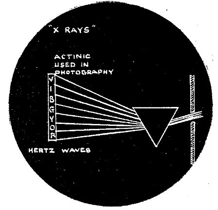
Fig. 1.
To better understand the nature of the Roentgen Rays we will observe quickly some characteristics of some waves of other lengths. In the lower part of the visible spectrum and extending down through four octaves of wave lengths we have the heat waves. One simple experiment will suffice. I pass the waves from this arc light through this filter made of carbon bisulphide holding iodin crystals in solution and remove all the light rays and then condense the remaining rays with this lense, and I am able to set this paper on fire or heat this platinum to a white heat. The relation of the light rays to the heat-producing rays can best be appreciated by this lantern view (Fig. 2) showing the relation of the heat rays to the light rays from the sun after passing through the moisture of the atmosphere, and this slide (Fig. 3), the relation of the heat rays of an electric arc to the light rays. In each the dark part from A to DC indicates the relation of the heat waves and their intensity below the visible spectrum and CD to E shown clear the spectrum from red to blue, and the heat waves therefrom, the line ABE indicating the intensity. You will observe that fully eight times as much of the energy of the arc light is given off in heat rays as in light rays. In the next (Fig. 4) we see the relation of many wave forms to each other and to sound waves.
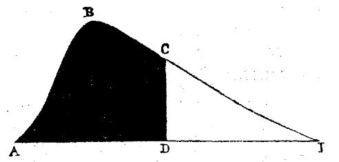
Fig. 2.
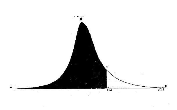
Fig. 3.
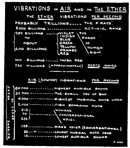
Fig. 4. Scale of Vibrations.
The waves of longer period or length do not appeal directly to any of our senses but we know that they exist from their effects. Marconi and others have invented eyes, to see as it were, some of these waves of other lengths. That is the function of the receiver or co-hearer used in wireless telegraphy. I have here arranged a working model. When I set these brass balls of this induction coil about an eighth of an inch apart and cause a spark to jump across, it is probable that the vibrations produced in the surrounding ether are at the rate of about sixty million per second, the waves being possibly a few miles from crest to crest. The wave length used is not known. You notice that as soon as I produce waves of this certain period this co-hearer receives them and closes the circuit of this battery which I have arranged by means of a relay to ring a bell. To show you how little effect distance has I will have someone carry it away through the building behind walls, etc. The model worked splendidly, so far as taken, responding each time the coil was excited; by this means Marconi has signalled ninety miles.
In a similar way wireless telegraphing, or signalling, is done at a great distance by waves of still greater length, magnetic waves, which we have not time to consider.
Ether waves of very short length, extending away above the visible spectrum into the so-called ultra-violet rays, including the Roentgen Rays, have the power of producing extensive chemical changes. Chief of these are the actinic rays so important in photography. You will see when I put this bottle of bisulphate of quinine in the ultra-violet part of the spectrum it glows. It is due to this power that we are able to use the Roentgen Rays. We allow these invisible rays to penetrate the tissues to be examined, and some of the rays are arrested or stopped according to the obstruction offered by the different parts of the field through which they pass, thus producing unequal chemical action on the plate. Hence the term shadowgraph. This hypothesis of ether waves of extreme frequency explains very clearly and plainly, practically all the phenomena of Roentgen Rays. There is another theory, that of material particles being thrown off by the anti-cathode which pass through the glass of the tube unobstructed. This theory is not so generally accepted. Its chief supporters, however, are Americans.
Before considering the sources of Roentgen Rays it would be proper to mention in this connection that the glow of certain insects and the fact that besides their luminosity they are able, through opaque substances, to produce effects upon photographic plates, and also this property of certain substances as uranium salts and radium and the dark rays of certain lights discovered by Le Bon are due probably to other waves of short length like the Roentgen Rays. These probably will be used for the same purpose some day.
The practical source from which we derive these Roentgen Rays is from the point of impact, opposite a concave cathode, when a current of electricity is discharged through a gas in a vacuum tube. Usually this point is a plain platinum surface placed at from forty five to sixty degrees to the direction of the cathode rays. These tubes may be excited by the discharge from an induction coil or a static machine or a Tesla coil or oscillator. As these devices have been quite fully described in current literature we will not stop to review them in detail, except to note the nature of a discharge through air.
This induction coil, you will remember, consists of a primary coil of a few turns of coarse wire surrounded by a secondary coil of a very great number of turns of very fine wire. When an interrupted or alternating current is passed through the primary, a current of very high voltage is induced in the secondary, demonstrating itself in discharges between the poles of the secondary. The phenomena are very beautiful in the dark as you observe between these two suspended wires. Lightning on a very small scale. The resistance of the atmosphere is so great that it takes probably several hundred thousand volts to discharge across that distance. When I place the discharging points closer together you see we get a continuous flame. When this discharge takes place through a tube partially exhausted, the phenomena are very beautiful. I have here a nice assortment of these tubes which I will now light up with the room darkened. You see both luminosity and fluorescence of the glass. At a certain degree of exhaustion the resistance to the passage of the current is very small. When I connect a lot of these Geissler tubes in series, you note besides the gorgeous display, they all together, in which the current has to pass through many yards, do not offer as much resistance as a half inch of air gap. This, by the way, is the principle on which Tesla proposes to transmit an electric current from this country to Europe, without wires. At a certain altitude the atmosphere will be of this minimum resistance and that stratum of air would constitute one path for the current and the earth the other.
I have some special tubes here also to demonstrate how the cathode rays produce fluorescence of certain salts and liquids. The display is very striking. Of the several methods for exciting the tube I prefer the induction coil, reasons for which can be brought out in the discussion. Next to the selection of the coil (I like the Ritchie very much), and almost of as great importance, is the selection of an interrupter. Until recently the vibrator was the most commonly used break and probably is yet, though I think it is destined to be supplanted by the electrolytic breaks. The mechanical breaks are usually very noisy and the mercury breaks often troublesome. The Tesla oscillators are very noisy.
With the electrolytic break or interrupter, the capacity of the coil is greatly increased. It was discovered less than a year ago by Dr. Wehnelt in Europe, and this form bears his name. It consists of a fine platinum wire from sixteen to twenty gauge protruding from a glass tube in which it is sealed and a lead plate, both in a bath of dilute sulphuric acid. It will work on forty volts. I prefer using it on the one hundred and ten and have the acid solution so dilute that it serves at the same time as a rheostat. Great trouble has been experienced in making the platinum points adjustable, which is very desirable, and yet durable, owing to the heat and action of the acid. I am happy to state that I have overcome this difficulty very successfully in the manner you see here, which is exceedingly simple. The platinum wire is soldered with twenty karat gold solder to a small brass bar of about the same diameter and the whole placed inside a piece of clay pipe stem about eight inches in length (Fig. 4½). The clay is not affected by either the heat or the acid, and while the apparatus is delicately adjustable it also is very durable; the pipe stem is adjustable through a rubber cork in the hard rubber top. I consider this form of interrupter very superior to any I know of. It has never failed to work in my hands since this arrangement was devised. Its construction is very simple, as seen by this drawing (Fig. 4½). Much could and should be said about the selection of tubes but time will only permit of a word or two. Deal directly with a reliable firm and use pretty high vacuum tubes. I have several forms. For a description of the most general forms I will refer you to Dr. Kell’s admirable paper before the National Dental Association last August. I must speak here of one form or rather addition I have made to tubes which is different, and superior for its purpose, to anything I have seen or heard of. It is for screening all the luminous rays from the tube, while allowing the Roentgen Rays to pass. It consists of a jacket of unvulcanized dental rubber. I use the red, as you see here, which is opaque to the X rays for all parts except where the rays are emitted, where I use a window of black rubber, through which the X rays pass unobstructed. This tube is used for making fluoroscopic examinations in total darkness. It works to perfection and serves the double purpose of assisting to prevent danger of puncture. In general I will say I like the Queen self-regulating tubes the best. My effort has been to reduce the time for getting good radiographs. Some of the best pictures I will show you this evening were taken in fifteen seconds through the dense jaws. This will be much reduced to five seconds or less, for the average, in part by placing a piece of fluorescence screen, specially prepared, each in front and behind the celluloid X-ray film and part, by using a tube of extra high current capacity. A new design of single focus alternating current tube of special merit made by Queen & Co., is shown in Fig. 4¾.
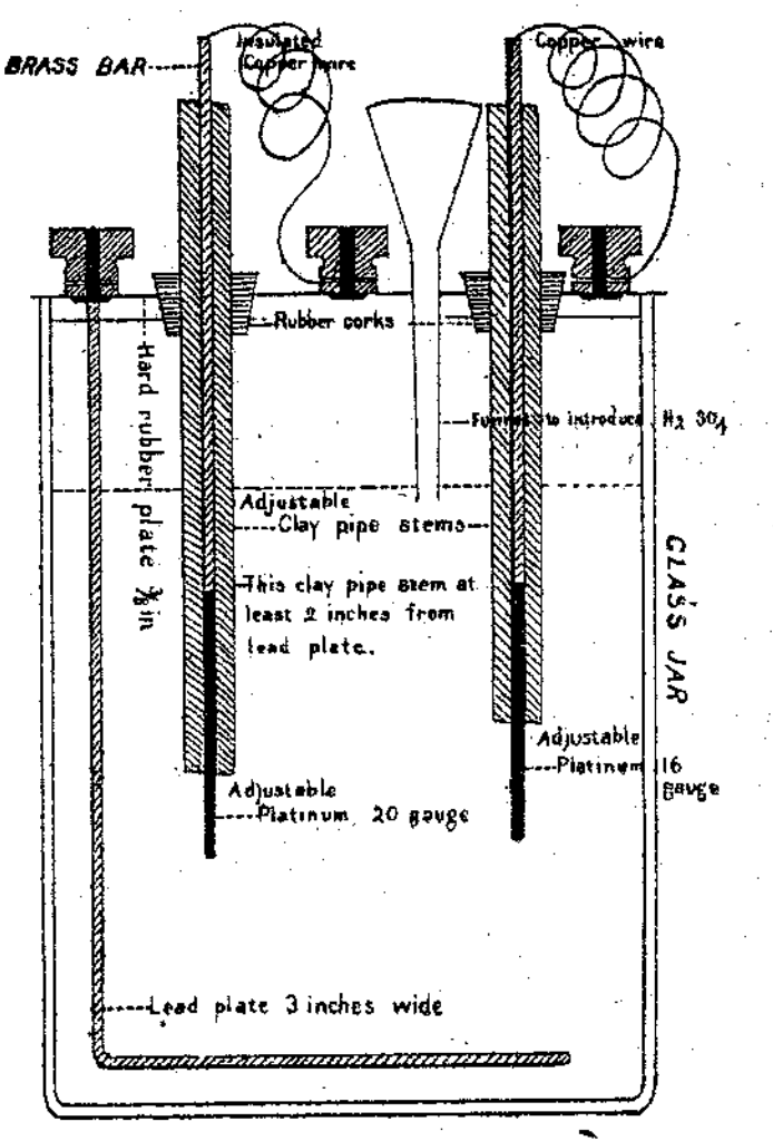
Fig. 4½.
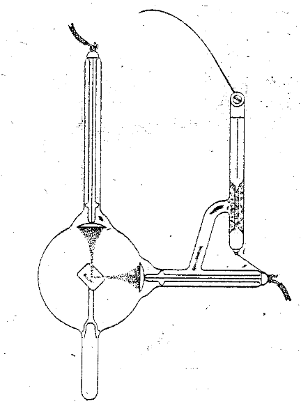
Fig. 4¾.
Every class of cases and ages require a tube of different condition and time of exposure, this requires a large assortment of tubes or adjustable tubes. This is the greatest factor in getting universal success and should be made the subject of a special paper. I may be able to give some hints when showing the practical cases. In our dental work the ordinary fluoroscope is practically of no use, except to show the condition of the tube. I have constructed some special screens which can be placed in the mouth and the shadow observed by a mouth mirror. This is only of service in a totally dark room, which this tube with the jacket is designed for. The same effect has been accomplished by others in a less convenient way.
By far the most important way for us to use the X rays is to make a negative. For preparing the plate for this, many methods have. been suggested. Some use entirely pieces of glass negative and wrap in black paper. Others use ordinary kodak film wrapped and sealed in black paper; some bind with lead or tin foil. To my mind, no method that I have heard of approaches in convenience and simplicity the one I suggested and reported in my lecture before the Northern Ohio Dental Society last May. It consists simply in placing a large piece of a specially prepared X-ray film which is quite stiff (Carbut’s preferred), between two layers of unvulcanized black rubber, and allowing the rubber to touch around the edges, where you dentists will best know how sure it will cling. This can now be cut through in any direction with a pair of shears, and simply pressing the rubber together where you have cut, seals a perfect joint. Of course this is perfectly impervious to moisture and light and at the same time offers almost no resistance to the X-rays. I put a piece of Eastman’s X-Ray bromide paper in also with its face to that of the film, thereby getting a photo direct and also serving a double purpose, in protecting the sensitive surface of the film. Occasionally it is an advantage to secure the plate with a special plate holder, but very seldom do I think it desirable or necessary. The plates prepared in the way I speak of are so convenient, you can bend a corner over thus (demonstrated) anywhere, thereby making the plate any desired shape or size, and of course the rubber adheres to itself and holds it firmly. The plates can generally be held in place with a finger to get the best results. You will observe a number on each of the slides exhibited. This is done by placing little figures on the outside of the plate-holder. They are made of fine copper wire prepared in advance and stuck on gum labels. It is a great convenience for keeping records, without danger of getting negatives mixed. I have experimented with many opaque inks but they are not so satisfactory. I have a very complete system of keeping all the records of each case, upon the envelope used as the negative preserver, which I will pass around. Note especially that the angles of the rays, the teeth, and the plate, to each other are kept in each case. This is very important and valuable since by it you can at any time determine the exact dimensions. Before proceeding with the practical cases I want to advise any intending investors to get a small glass-top table on large, rubber-tire castors, or wheels, for keeping your coil, and accessories, which are few, upon. Also note that it has recently been shown that the time for exposure is in direct proportion to the distance and not to the square of the distance as has been generally thought.
We will now see some lantern views of practical cases and one or two typical pictures will suffice in each of several classes of cases in which the Roentgen Rays are specially well adapted for diagnosis. Unfortunately a great deal of the detail and information is lost as compared with looking through the negative itself. Photos, even contact prints, lose about half their detail. In good negatives even the cellular structure of the bone is distinctly shown. This is mostly or entirely lost on the screen or in the half-tone used for illustration, so you will have to make a great deal of allowance.
For the location of unerupted teeth it is simply perfection. Fig. 5 shows the condition of the superior arch of a boy at ten years of age. Two generations preceding, on his mother’s side, had been lacking the superior laterals. She presented him to have steps taken to prevent the shedding of his deciduous laterals to make them permanent. You can scarcely imagine the joy of that mother, who herself suffers considerable disfigurement, from this cause, when she saw the radiograph showing the development of these teeth that had been the object of her cherished but abandoned hope.
Fig. 5.
The next (Fig. 6) illustrates the condition in a case of delayed dentition of the bicuspids. The cuspid has been erupted for some time and the first deciduous molar shed by this eruption. This superior arch is exceedingly retracted. The radiograph shows that but one bicuspid has formed and it is thrown out of its course by about twenty degrees. It is absorbing the anterior buccal root of the first permanent molar. A course of treatment is quickly suggested.
Fig. 6.
In the next (Fig. 7) is a typical example of the appearance of cases where a permanent tooth fails to form and the deciduous is retained. In this case an inferior deciduous molar. A lady of about thirty years of age discovered that she still had a baby tooth and felt so ashamed of herself that she hurried to the office to have it extracted. The radiograph settles all hope of it ever having a successor.
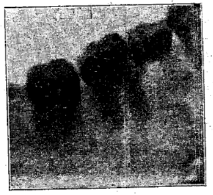
Fig. 7.
I will now show you a wonderful picture demonstrating the very early calcification of the enamel of the permanent teeth (Fig. 8). It is taken of the superior arch of a baby boy of fourteen months, who has no deciduous teeth erupted yet in this arch. The radiograph shows not only the development of all the deciduous teeth, but also the commencement of calcification of the permanent centrals. But this is not all. While his father is lacking his permanent laterals we can see clearly in the negative, which was a ten second exposure, even at this young age the crypts forming for his permanent laterals. I know of the joy of that boy’s father at this information, for he is my boy.
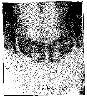
Fig. 8.
An example of lost teeth is shown in the next, (Fig. 9), which indicates the whereabouts of the missing bicuspids. There are very many cases of this class.
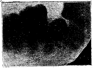
Fig. 9.
The next (Fig. 10) shows a lady’s superior arch at about thirty years of age. When this picture was taken she was still waiting for her permanent teeth to erupt, but she need not wait longer for this lone second molar is all she is to have on that side. Five teeth are lacking on that side and three on the other.
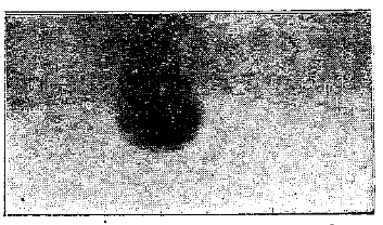
Fig. 10.
In no class of cases is this means of diagnosis of more frequent service than for exploring the various deep pathological conditions. For example, the extent and location of abscesses, the direction and path of the fistula, and of very great importance, the most dependent point of the abscess. This picture (Fig. 11) shows the appearance of a blind abscess at the apex of an inferior incisor. It shows which tooth is affected and that no teeth in this vicinity have root fillings to suspect as imperfect.
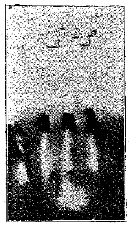
Fig. 11.
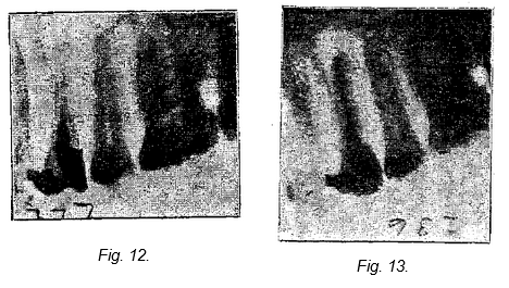
In the next (Fig. 12) we have some information regarding a case of neuralgia of uncertain cause of years standing undoubtedly caused, as proven later, by the blind abscess at the apex of the first superior bicuspid. The abscess was evidently caused by imperfect root-filling, which is clearly shown to only extend halfway to the apex. On opening up the canal I found putrescence in the apical half of the canal. This negative shows beautifully the cellular structure of the bone.
The next picture (Fig. 13) shows the same root filled to the apex. The blind abscess was drained through the buccal wall of the process.
These abscesses vary greatly in extent and their exact extent is clearly shown in good radiographs, as for example in this picture (Fig. 14) which shows a blind abscess of considerable dimensions, and of years standing, during most of which time it has been almost continually under treatment, so the patient informed me, through the root canal of the lateral where it had its inception. The lateral is the tooth nearest the figure 3. These numbers, you remember, are produced by placing metal figures, made of fine copper wire stuck on gum labels, upon the outside of the negative cover, when the exposure is made, and are invaluable for keeping records correct, and for identifying negatives. This picture shows beautifully the most dependent part of the abscess, which I have marked X, and the folly of trying to drain it through the root-canal. On establishing free drainage at X, by drilling through the process, and thoroughly sterilizing and cauterizing the pocket, a permanent and perfect cure was effected in a very few days.
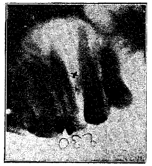
Fig. 14.
In this next picture (Fig. 15) we have an exceedingly large abscess, and also one of long standing. It had a fistula beside the second bicuspid. The dentist sending the case for radiographing had labored faithfully, but with unsatisfactory results, to cure it. A crown on the lateral had been destroyed to examine the root-filling beyond it, and the second bicuspid had been extracted and replanted in search of exostosis. The radiographs taken in sections, show the root of the lateral to be largely absorbed and a series of pockets difficult to drain between the roots of the various teeth. It also shows the abscess to extend beyond the anterior buccal root of the first molar.
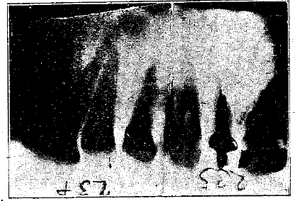
Fig. 15.
The picture now before us (Fig. 16) shows a remarkable change of bone structure taking place around a superior central incisor, one that had, a couple of years previous, received a hard blow, since which time it has been constantly elongating, though it is very solid in its attachments. The negative shows clearly the old base for the apex from which it has advanced, about three-sixteenths of an inch. It is an interesting study in pathology. The bone, though forming an unusually firm attachment, is evidently less dense than normal, and slightly honey-combed in structure. The peridental membrane is almost obliterated.
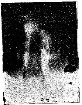
Fig. 16.
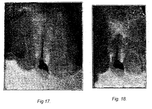
In the next picture (Fig. 17) we have another blind abscess with its evident cause, viz.: imperfect root filling. The case was of thirteen years standing and had received extended treatments. I amputated the tip of the root, without extraction, at the point where the root-filling ended as shown by the radiograph (Fig. 17) and with splendid results. The next picture shows the same tooth after the root amputation (Fig. 18).
In the next picture (Fig. 19) we see how beautifully the bone has adhered around the stub of one of these amputated roots. This amputation was made in January, 1896. The patient claims it to be the strongest, solidest tooth she ever had.
Fig. 19.
In the next (Fig. 20) we see broken broach protruding through the apex far into the tissue.
Fig. 20.
In this picture (Fig. 21) we see much of interest. The radiograph was taken to locate a piece of a cambric needle which the patient had broken in the root while trying to relieve an abscess. It was thought to have been forced through into the tissue as the apex was found open. It is easily seen lodged in the root which was evidently bifurcated. This picture also shows beautifully the relation in this case of the teeth to the antrum. You will observe that the roots of the second molar penetrate nearly half way up through that cavity.
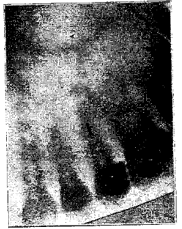
Fig. 21.
The value of Roentgen Rays in Orthodontia is almost beyond calculation for it enables us to see just how our force is being expended. Probably the greatest factor in that work is to move the roots as well as the crowns. In this picture (Fig. 22) we see an attempt to draw two teeth together when alas only their crowns have been tipped toward each other.
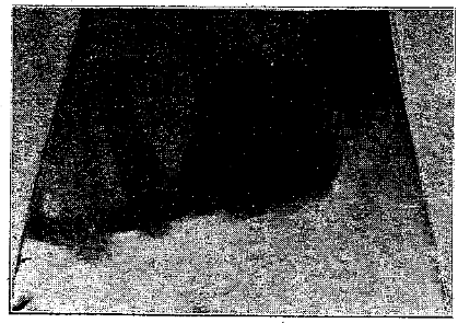
Fig. 22.
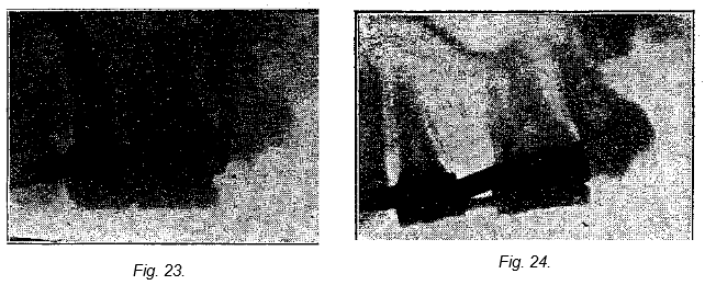
This next picture (Fig. 23) shows the commencement of a case where separation the width of a tooth (one having been recklessly extracted) is required. And in the next picture (Fig. 24) we see how well this has been accomplished. Unfortunately, time only permits of one example of each of a few classes of cases out of a great many.
The next (Fig. 25) shows beautifully the fit of these crowns and the depth of a pyorrhea pocket, supposed, marked X. The radiograph shows a perforation in the wall of the root of the first bicuspid through which cement has been forced into the tissue producing the suppuration and absorption, supposed to be a pyorrhea pocket.
Fig. 25.
In this next picture (Fig. 26) which is the last, we have an example of the service of the Roentgen rays in determining the location of third molars. This one is not erupted at all and lies at just right angles to its proper position as shown by the second molar. It would certainly be a difficult one to extract if you did not know its position.
Fig. 26.
Gentlemen, we must not take time for more and I ask your pardon for keeping you so long. I thank you for your patient attention. I will be glad to allow any one interested to make observations with the Roentgen Rays or examine the apparatus after the dismission, or to ask questions.
I want to thank Prof. Thomas, of the Ohio State University, for his great kindness in helping me out of a predicament this evening. The coil I expected to use, which you see here, was so roughly handled in the express that it was disabled, and he very kindly brought me down one from the University at the last moment.